This post came a bit later than I intended, sorry for that! When I wrote the previous post I intended to start working on this post immediately, but this didn’t go as planned…
Anyway, now I finally have my final post ready. For me this marks a milestone in this project: As of this post, everything which is required to build a Flyball ETS is available online. I look forward to hearing about peoples experiences in building it, and seeing other versions with possible improvements done to it.
But enough of me rambling on, let’s get to the juicy parts: How to put together all components for Flyball ETS!
This post provides instructions assuming that you have already built the housing assembly, complete with the cavities for the lights and LCD display routed out, and the holes for the photoelectric sensors drilled through. see my previous post again to have all the plans.
Mounting holes
We start by preparing the mounting holes for our PCBs, LCD and battery charger components, since these are a lot easier if all the other stuff is not yet in the housing. The nylon spacers and screws we ordered are M3 (0.5mm pitch) threaded, I found that it is really easy to put M3 thread directly into the PVC foam board, we can do this by using a 2.5mm drill, drilling about 8mm deep (leaving 2mm of PVC foam board), and then using a standard M3x0.5 tap to create the thread. I found it quite hard to get the drill and tap dept right, so I ended up putting a piece of colored tape on my drill and tap to see where I should stop drilling, it would be shame if your nice housing shows a hole on the outside because you drilled too deep :-).
Feel free to put the PCBs wherever you want, I ended up arranging mine like so:
- Inner backside (mounted vertically):
- Sensor board
- Lights board
- 220V input and charger components
- Mounting plate (mounted horizontally under LCD)
- Mainboard
- Power distribution board
- Bluetooth board
- Remote control receiver board

When positioning your PCBs, make sure to leave enough room
for other components, also keep in mind that you have to install 20 photoelectric sensors, so you need to leave some room to route the cables up/down the middle plate. Take a look at the picture to the right to see how I’ve positioned my PCBs and routed the cables.
Once you have determined where you put your PCBs, mark the holes with a pencil, once you have all the holes marked, start drilling and tapping all of them. When you have all the holes tapped, put nylon spacers in each of them, with the kit I suggested you won’t have enough spacers of the same lenght to accomodate PCBs, so use the longer spacers for the lower-profile PCBs which can be a bit higher without problems. When the spacers are in place you can mount the PCBs to them, step 1 completed 🙂
Battery and charger components
In the meantime, after about 6 months of use during flyball practice (twice a week) the battery charger that came shipped with the battery I suggested, gave in and stopped working. No surprise really since the charger was included for free with the battery, and the battery was dirt cheap by itself already. So I had to come up with a better solution to charge the battery.
I ended up ordering a 110-220V AC to 18V DC power supply, and a separate battery charger circuit.
Since our battery has to be charged to 12.8V in order to be full, a 12V power supply is not enough to achieve this, therefor we needs the next available voltage, which is 18V. The charging circuit I suggested has 3 potentiometers which can be adjusted to regulate 3 charging parameters:
- Charging voltage: This needs to be set to 12.8V
- Charging current: This needs to be set to a ‘safe’ value. You can find a lot of discussions about what’s safe and what’s not. I decided to set it to 500mA, this should be well on the safe side, and leaving the gates plugged in a night will be more than sufficient to charge them.
- Trickle charge LED turn on threshold.
I will explain shortly how to setup the charging module:
First, connect the input of the charging module to the 18V power supply, do not yet connect the battery to the charging module. Use your multimeter to measure how much volt the module is outputting, turn the first (left potmeters when looking at board with potmeters at the top). Turn the potmeter up/down until the module outputs 12.8V
Now, we need the battery almost empty, take care to don’t deplete the battery below 9.6V, as that could damage the battery. Not connect use your multimeter in the DC Amp setting and connect it in series between the battery and the charger. Now turn the 2nd (middle) potmeter up/down until the charging current on your multimeter shows 500mA (0,5A)
The 3rd potmeter (right one) is slightly more difficult to set up, this one controls when the ‘trickle charge LED’ is lit. When your battery is being charged, the charging current (which starts off at the 500mA you’ve set it to in the previous step) gradually decreases as the battery becomes charged. When the battery reaches 12.6V (the charging voltage we set it to) there will be nearly no current flowing anymore, and the battery is considered charged 100%. So we need to identify a nice spot at which the LED will turn on that tells us the battery is fully charged. The easiest I found do this is as follows: When you start charging your battery in the previous step, disconnect your multimeter, configure the multimeter again to monitor voltage, and connect it to the output of your charging module. You will now see the output of the module increasing as the battery becomes charged. Once the voltage reaches about 12V, the battery is about 70% charged, start playing with the right potmeter until you find the point where the trickle charge LED turns off/on (it fades slightly before turning off). Turn the potmeter up so that the LED is just off. Now monitor the charging circuit and keep increasing the potmeter setting until the LED turns on when the battery reaches about 12.2~12.3V, this is about 80-90% of the total capacity and is a good point to consider a full charge. You could set the LED to turn on at 100% (12.6V), but charging these last 0.1V’s goes so slow it would take a lot longer to reach this level.
I plan on making a video on this to clarify how to configure the charging module, no promise on when though 🙂 !
I also changed the battery on my shopping list to a new type which does not have a built-in power switch and LED. The original battery which I suggested had these, and since we would leave the battery switched on while it’s built-into the housing, the LED would drain the battery over time.
Find a good spot to mount the battery and mount it so that it can’t slide around. I used 3M Dual Lock to mount my battery, it’s an awesome hard velcro-like stuff which makes for a really strong mount but can be detached and reattached later on.
If you ordered the original battery I suggested (this one):
Then you should remove the LED from the battery, or it will drain the battery slightly, it’s right next to the power toggle switch. You have to cut the wrapping foil around the switch carefully, just enough so you can pry out the switch, if you pull out the switch you’ll be able to pull out some extra cabling with the LED soldered in between. Just cut out the LED and isolate the wire ends so they can’t touch anything. Take care when pulling out the switch to not damage any of the wires, they’re quite small.
Switches and wiring
Next part you should do is prepare the switches for installation, and prepare the necessary wires to connect everything together. Make sure to make your cables a little longer as required to have some extra wire to organize them neatly
Power switch
For the power switch we need to route both +12V and GND to the switch, since it has a built in LED, so make a cable which goes from the barrel jack output of the battery to the power switch. The switch you ordered normally has 5 pins:
- +
- –
- C1
- NO1
- NC1
You need to wire them up like so:

This will ensure the LED in the switch turns ON when the button is in the ON position. The button then provides 12V power to the power distribution board.
Laser dot sight push button
The waterproof push button I suggested will control our laser dot sight. The button will be wired to the trigger input of the 555 timer chip on our lights PCB. The 555 will then power the output pin for a variable amount of time, how long can be adjusted by the R1 trimpot on the PCB. I set mine to 60 seconds. The reason why I made a 555 circuit for this, is that I don’t want the laser sight active at all times, since it might blind the dogs. A simple push button would have also worked, but then you couldn’t let go of the button while aligning the gates.
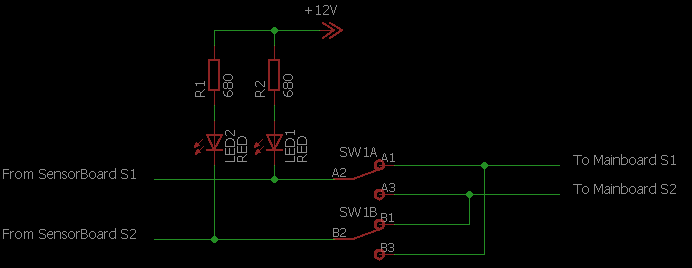
Sensor swap switch
The DPDT (double pole double throw) switch will be used to swap the pin mappings from sensor columns 1 and 2 to the arduino. Our software expects S1 to be the handlers side and S2 to be the boxes side, so depending on which side of the lane we want to put the active sensor gate, we need to be able to swap around these pins. If you’re sure you can always put the active gate on the same side, feel free to leave out this switch.
Wire the switch like shown in the schematic below, measure which contacts are closed when the switch is in each position first, then connect the switch so that that the position of the latching push button faces the box side, so that when it is unpressed (button sticking out), the box should be at the buttons outer side, and when it’s pushed in, the box should be at the switches inner side, this helps remembering how to set the switch for which situation.
The 2 LEDs should be wired to the sensors (before the swap button!), the led’s should be installed somewhere visible, I put mine in the top cover of the active gate. The LED’s will show the status of the sensors, it is helpful when aligning the sensors. When the sensors see the reflection (so beam not broken), the LEDs will be OFF, when the sensors do not see the reflectors (beam broken), the LEDs will be ON.
Lights
First we must prepare the light PCBs to go into the sides the active side gate. One light will be made up out of 4 pieces of 5cm RGB LED strip. On each side we need the following 5 lights, from top to bottom:
- White
- Red
- Yellow 1
- Yellow 2/blue
- Green
So actually we need only one light which needs to be able to show 2 colors, all others can be configured to only show one color.
For sake of ease, I made all 10 LED panels up equally, meaning all 3 colors are wired, while this is not technically necessary, it prevents mixing up different panels, and allows for relatively easy color changing in the future (or for other flyball formats, like e.g. the American format where I heard they don’t use color coded fault lights).
The LED panels are the single most cumbersome task about this whole build, for one panel, you have to cut and strip 12 pieces of wire, and then make 24 solder joints. So by the end you’ll have made 120 pieces of stripped wire, and made 240 solder joints, good luck 🙂
Making the LED panels is quite easy, you take a 20cm piece of RGB LED strip, cut it unto 4 pieces of 5CM (3LEDs) each, glue them horizontally adjacent to a piece of PCB, and then connect them again to eachother using 4 pieces of wire for each 5cm strip.
See some pictures below which show how the LED panels are made up.


Sensors
This is probably the easiest part, just insert all sensors into the holes you drilled earlier. One thing to take care about here, is that the front of the sensors (where the IR beam comes out) should be as close to the acrylic glass plate as possible. If this is not the case, the glass plate will act as a reflector and cause the sensors to not pickup any crossing dogs.
Make sure you test each sensor separately by looking at the LED at the back of the sensor, with the glass plate held in front of the sensors.
Once all the sensors are in place, you have to route the wires, cut them to length, and put JST connectors on them so they can be plugged into the sensors PCB.
The sensor PCB has one set of connectors labeled ‘S1’, and another one named ‘S2’, make sure you connect one column of sensors to the S1 part of the PCB, and the other column to the S2 part of the PCB. Where they are plugged in within the S1 and S2 groups of connectors, does not matter at all.
We will install a switch that allows us to toggle the handlers and box side of the sensors, but by default, the S1 connectors should connect to the handlers side, and S2 should connect to the boxes side.
Spirit bubble levels
The spirit bubble levels should be installed on top of the gates. These will help to ensure the gates are nicely level, before trying to align them.
To install the spirit bubbles you have to drill out the space in the top piece of both gates, the spirit bubbles should be 8mm thick, so you have 2mm spare to stop drilling. After you’ve drilled the holes, just take some silicone and glue the bubbles into place. The tricky part here is to make sure the spirit bubbles are nicely aligned to the actual gates themselves. Try to position your gates nicely level using a big spirit bubble (like this) in both directions, and then when gluing in the small bubbles, try to get them to match as close as possible.
Closing thoughts
I’m happy I got this post finished, albeit a lot, like really a lot later than I intended. Nevertheless this puts the project at a point where everything you need to build your own ETS is available. Because this last post took so long, I’ve heard from several people who started building the system, most slow but successfully so far.
Have I forgot something? Are you building your own ETS ? Let me know in the comments below!

Prachtig ontwerp,ik ben zelf aan een project bezig voor twee banen al weet ik nog niet hoe ik ze op mekaar ga afstemmen.
LikeLike
hello, i don’t read anything about Bluetooth board and Remote control receiver board ?
Can you explain me more please ?
LikeLike